Valve Adjustment
Valkyrie
Valve Adjustment
Documented by Carl Kulow
Picture's by LaMonster
Tools
Allen sockets –
5mm, 6mm
ratchet
short extension
oil drain pan
newspaper
sockets – 17mm
box wrench –
10mm
feeler gauges
screwdriver
Start Here
1.
Engine cold!!!
2.
Bike on sidestand
3.
Transmission in neutral!!!
4.
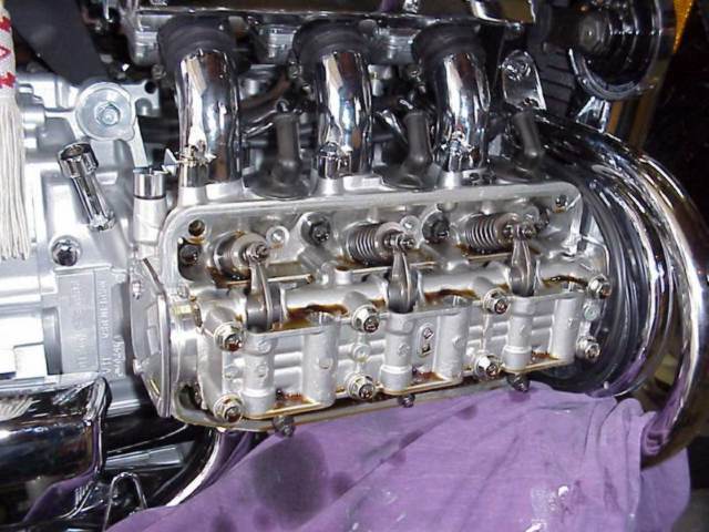
Remove both cam end covers, 3 inch square covers with one
rounded side, 2 bolts each (5mm hex) at the rear end of each valve
cover
5.
Place an oil drain pan under the left valve cover (~1/8 cup
will drain), newspaper under the right valve cover (a few drops will
drain)
6.
Remove the rubber plugs from the center of the valve cover
bolts
7.
Remove both valve covers (6mm hex) – be sure the
washer/sealing ring comes off with each bolt!
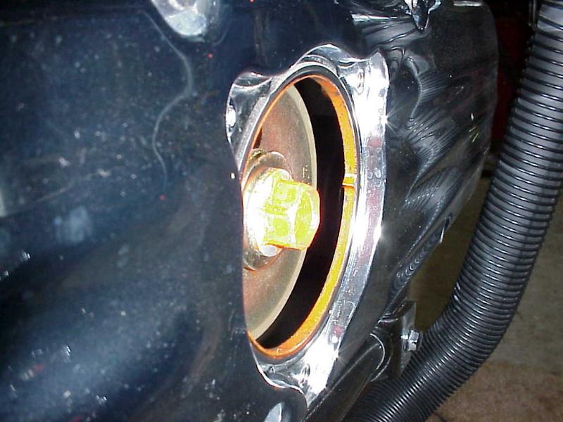
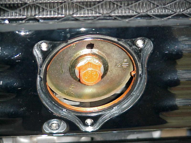
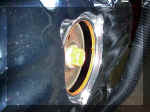
8.
Remove the timing cover, 3 inch round cover directly below
the radiator, 3 bolts (5mm hex)
Hint: Any of
the covers removed above may stick slightly and you will need to tap
them gently with a wooden or plastic screwdriver handle or the palm
of your hand.
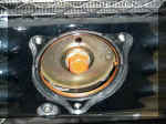
9.
With the transmission in neutral, turn the crankshaft (17mm)
where you removed the timing cover, counterclockwise (there is an
arrow on the timing plate) and align the T1,2 mark on the timing
plate to the index mark on the outside at 3 o’clock
10.
Be certain the No.1 piston is at TDC (Top Dead Center)!!! –
the intake and exhaust valves for No.1 should wiggle slightly in and
out. If not, turn the crankshaft a full 360 degrees counterclockwise
to the same T1,2 mark and check the valves again for “wiggle”
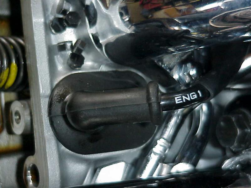
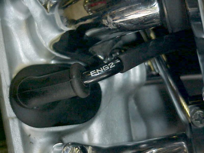
Cylinder Location
(the spark plug wires are also numbered as given below)
Right side,
front to rear = 1, 3, 5
Left side,
front to rear = 2, 4, 6
Valve
Clearance
Intake =
.006in. (.15mm)
Exhaust =
.009in. (.22mm)
Valve
Location
Intake
Valves are on the top (take air/gas in from the carbs)
Exhaust
Valves are on the bottom (exhaust to the exhaust pipes)

11.
Insert the correct feeler gauge between the valve
stem and the adjuster screw. There should be slight drag on the feeler
gauge – be sure that you do not have the gauge canted or curved as you
are measuring. You can use the “go, no go” method – a .008in.
gauge should not go into the .006 intake; a .011 should not go into a
.009 exhaust if adjusted properly. A .007 gauge will go into the intake
and a .010 gauge will go into the exhaust, but will give a too tight
drag.
12.
If any valve needs adjusting, loosen the adjuster
lock nut with a 10mm box wrench and turn the adjuster screw with a
screwdriver to get the correct clearance – slight drag on the feeler
gauge.
13.
Slide the box wrench over the shaft of the
screwdriver and hold the adjuster screw with the screwdriver while
tightening the lock nut with the 10mm box wrench.
14.
After tightening, double check the clearance.
15.
Turn the crankshaft 120 degrees to align the T3,4
at the index mark. Check for wiggle at No.4 valves. Adjust if necessary.
16.
Turn the crankshaft 120 degrees to align the T5,6
at the index mark. Check for wiggle at No.5 valves. Adjust if necessary.
17.
Turn the crankshaft 120 degrees to align the T1,2
at the index mark. Check for wiggle at No.2 valves. Adjust if necessary.
18.
Turn the crankshaft 120 degrees to align the T3,4
at the index mark. Check for wiggle at No.3 valves. Adjust if necessary.
19.
Turn the crankshaft 120 degrees to align the T5,6
at the index mark. Check for wiggle at No.6 valves. Adjust if necessary.
20.
Install the timing cover, 3 bolts (5mm hex)
21.
Wipe any oil off the valve cover gaskets
Hint: You
may need to apply a small amount of TRV or similar sealer to each
outside end of the cam housing. There are two spots at each end, top and
bottom, of the round cam housing where the factory applied some sealant.
In any case, be sure that none of the factory applied sealant is balled
up and potentially keeping the valve cover gasket from sealing tightly.
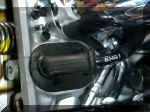
22.
Below and to the front of the right valve cover,
remove the two sets of wire cables from the wire holder and gently pull
out any extra slack to make it easier to reinstall the right valve
cover.
Hint: Do not
over tighten any of the bolts to the 5 different covers when
reinstalling. These are relatively small and fine threaded bolts and
could easily break or strip. Keep your palm or fingers close to the head
of the ratchet when tightening these bolts.
23.
Insert the six valve cover bolts and washers (6mm
hex).
24.
Insert the wire cables back into the holder
25.
Install the left valve cover, 6 bolts and washers
(6mm hex)
26.
Install both cam end covers, 2 bolts each (5mm hex)
27.
Insert the black rubber plugs into the valve cover
bolts
28.
Run the engine; check for oil leaks
|
The author has done his best to produce
accurate information
however; neither he nor the editor nor the web publisher can
assume
liability for any damage or injury caused by any errors or
omissions in this manual
Use good sense and at your own risk!
|
|
 ShopTalk