DisclaimerInformation has been provided on these pages
in hope that it will be useful.
|
|||
Attribution:Kudos to Cruisin' Dave (Dave Sproul) for coming up with such a wonderful mod. Many motorcycle riders around the world are now benefiting from this setup. I believe that this is presently the neatest most useful mod on my Valkyrie Tourer. Thanks Dave!!!! This mod was made possible with the help of many guys on the VRCC Tech Board (in this case, especially Joe Byrd who has walked me through each step of his installation and also Þrúðr who filled in the gaps when I hollered for help/info). The following has also been inspired by the excellent write ups listed in the Links section at the bottom of this page. Other than adapting this setup to my Valkyrie Tourer, I didn't invent anything. All ideas, modifications, etc. were taken (borrowed, copied, etc.) from different sources as explained above and throughout this write-up. If I have borrowed something from your web site and have forgotten to mention it, please let me know and I will correct the situation immediately. I can easily be contacted through the VRCC Tech Board. My handle is QueXpress.
|
|||
|
Note:
Click on any image to |
|||
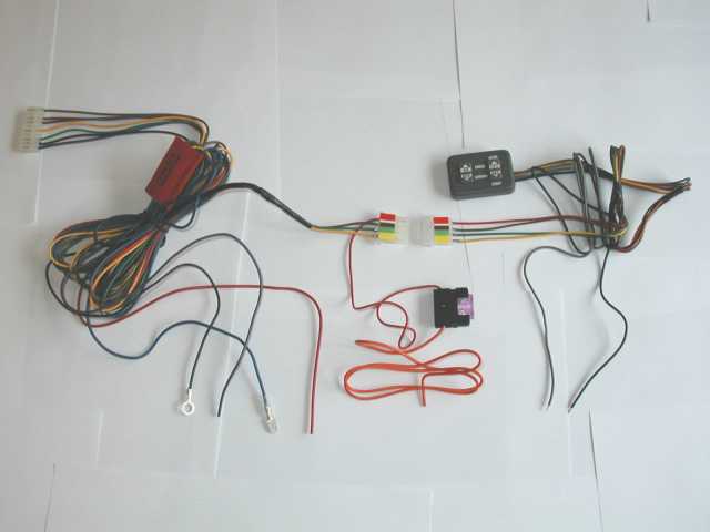
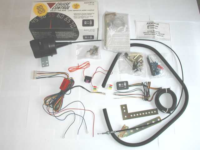
Audiovox CCS-100 Cruise Control Kit: Parts Received/Used When adapting this cruise control to my Valkyrie,
the following parts have been used: |
 |
||
Audiovox CCS-100 Cruise Control: Parts Required/Purchased/Fabricated
|
|||
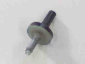
Check Valve:Part number 730-1347 at NAPA. At AutoZone,
Pep Boys, etc., look in the Help section for part number 47149. It will
be in a little red package named HELP. Tip from John Schmidt: Electronic shrink wrap (with glue inside) could have been used instead of duct tape.
|
 |
||
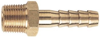
Brass Hose Barbs:3 brass hose barb to NIP adapters (3/16 X 1/8) were picked up at a hardware store.
|
 |
||
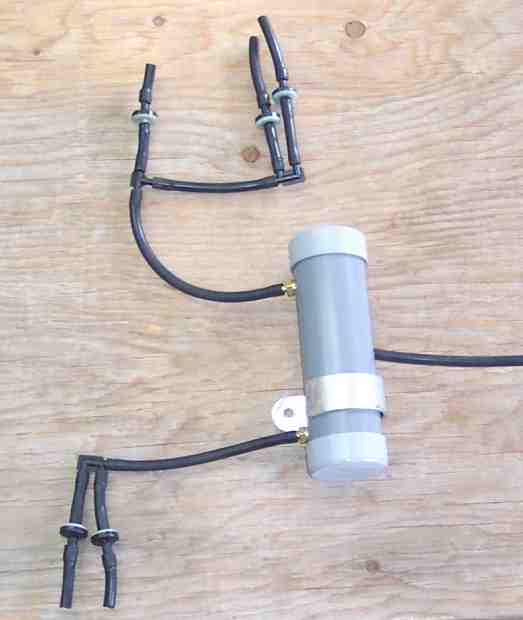
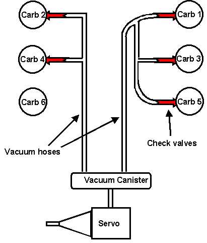
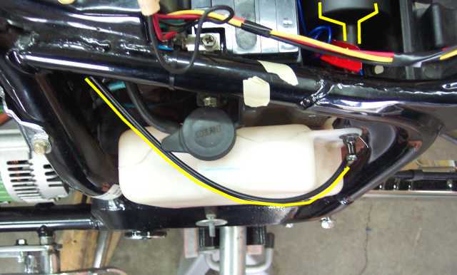
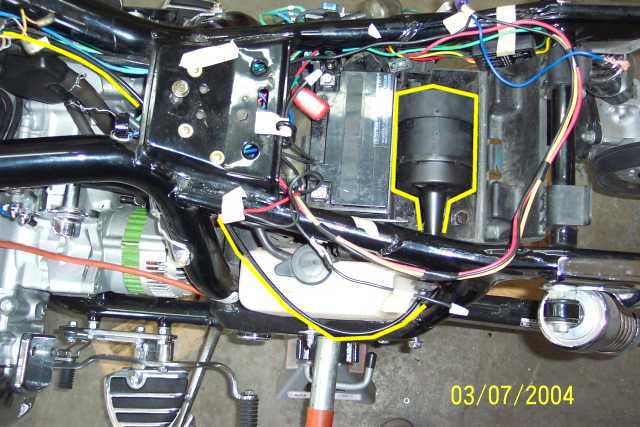
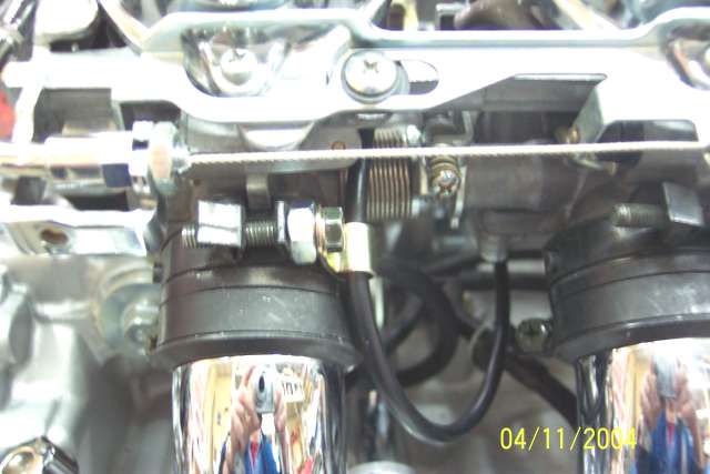
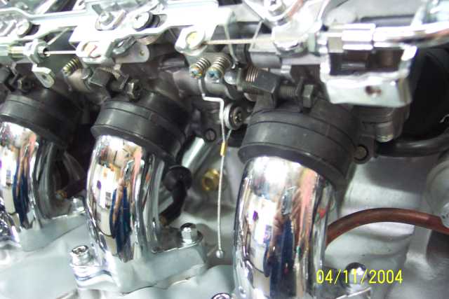
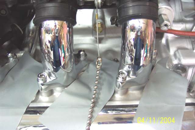
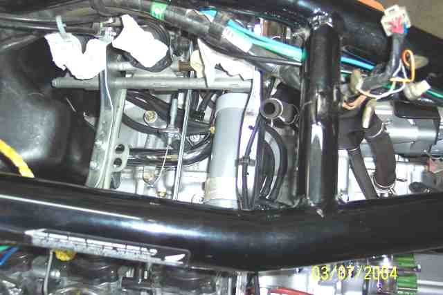
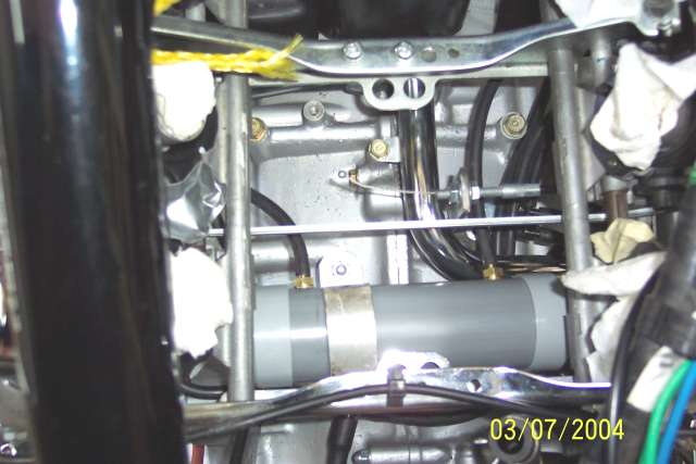
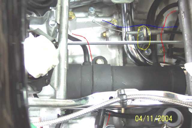
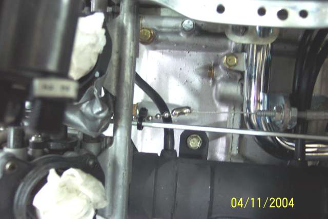
Vacuum Canister Setup:The CCS-100 requires constant vacuum to supply mechanical power for the throttle actuator. A vacuum canister has been fabricated to satisfy this need. The canister is a 6 inch X 2 inch PVC pipe with caps at each end. A piece of aluminum was wrapped around it in order to make a bracket (to fasten it to the top of the engine). The canister is connected to 5 vacuum ports (with a check valve on each port). You can see the 5 check valves, and how the tubes are set up. The 3 at the top of the pic go to the right bank (all 3 cylinders), and the 2 bottom ones to the left (cylinders 2 and 4). 3 holes were tapped into the PVC canister and JB Weld was added to the threads before screwing in the hose barb to NIP adapters (3/16 X 1/8). 2 barbs point towards the front for the intake ports, and one points a bit downwards and towards the rear of the bike. This tube continues under the battery box and then up towards the tool portion of the battery box.
|
|
||
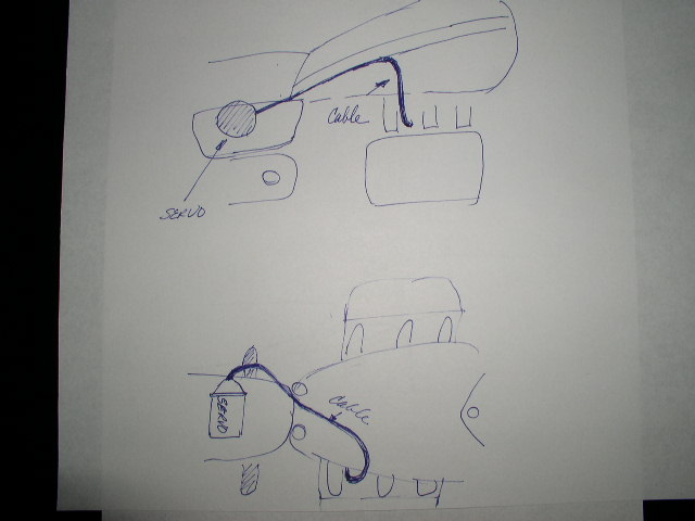
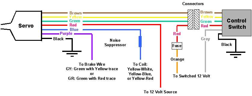
Vacuum Setup Diagram:This is a simplified diagram of the complete vacuum setup for the cruise control on my Valkyrie Tourer.
|
|
||
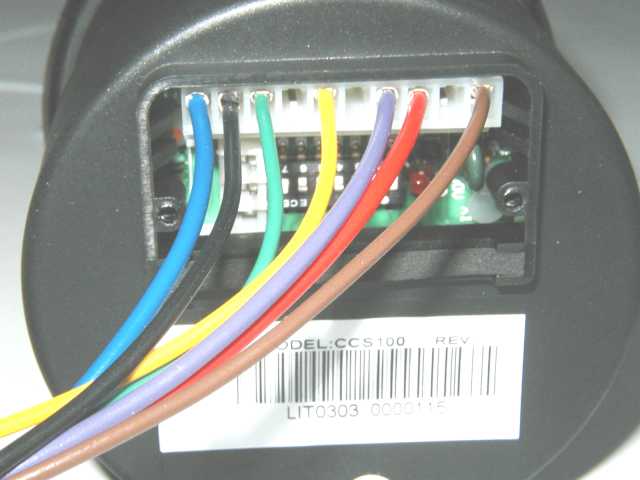
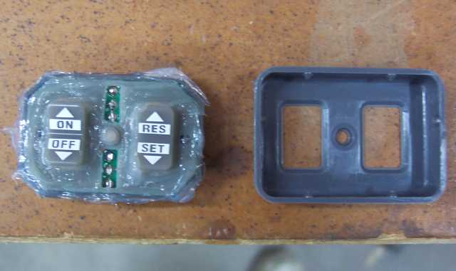
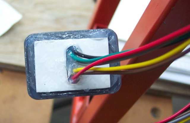
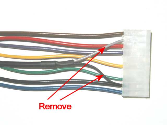
Modify Servo Wiring Connector :Remove and discard the black/gray pair wires.
|
 |
||
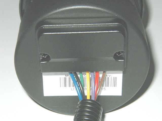
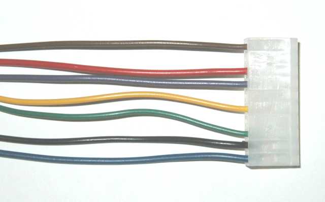
| Modified connector with the black/gray pair removed |
 |
||
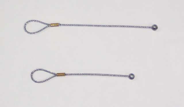
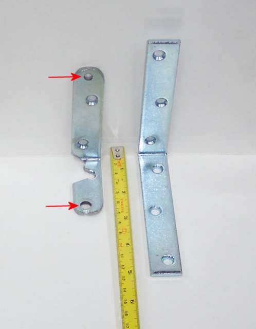
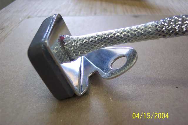
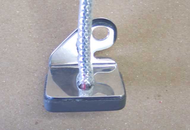
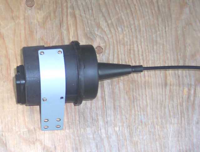
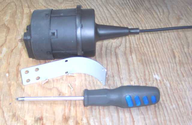
Servo Setup:Remove the metallic strap attached to the servo.
|
 |
||
| Strap removed. |
 |
||
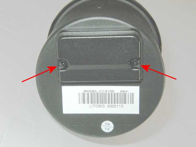
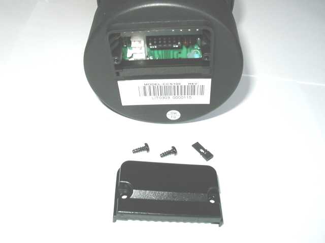
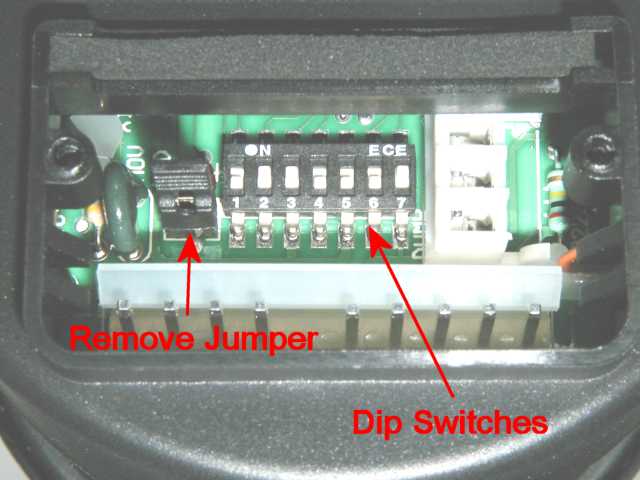
| Remove small cover to setup the servo. |
 |
||
| You now have access to the DIP switches, jumper, LED, etc. |
 |
||
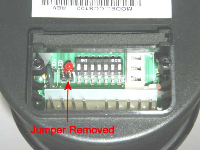
| Remove the jumper (under the LED, next to the DIP switches) to specify that the cruise control unit is being installed in a manual transmission vehicle. |
 |
||
| Black jumper removed |
 |
||
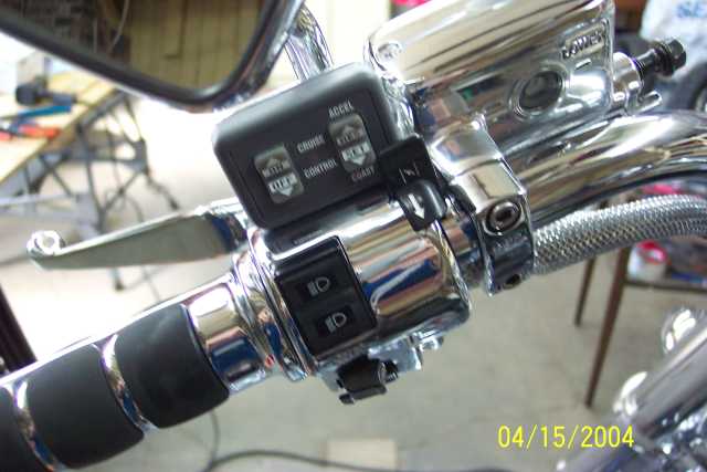
DIP Switch Settings Used On My Honda Valkyrie: |
|||
| SW1 | ON | Set the Pulses Per Mile for the necessary manual transmission rate of 4000 |
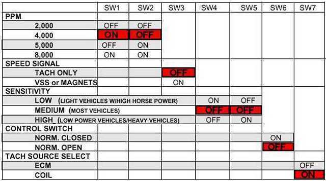 |
| SW2 | OFF | Set the Pulses Per Mile for the necessary manual transmission rate of 4000 | |
| SW3 | OFF | Set the Speed Signal for Tach Only | |
| SW4 | OFF | Medium sensitivity (I have tried LOW, but MEDIUM functions much better) | |
| SW5 | OFF | Medium sensitivity | |
| SW6 | OFF | To use the included Control Pad | |
| SW7 | ON | Select“coil” as the source of timing pulses | |