Engine Coolant Temperature Mod or ECT ModSubmitted by: Airetime
|
||
|
|
|
|
|
Picture 1 |
Picture 2 |
Picture 3 |
|
|
||
Overview:Want better mid-range performance and better mileage? Up to now, the choice has been to use a timing wheel that uses a fixed advance of either 4 or 6 degrees. Two drawbacks of mechanically advancing your timing is that some have difficult cold starting problems, and the loss of power at the high RPM's. An alternative? Utilize the function of your Engine Coolant Temperature sensor or ECT sensor circuits already in your ECM and you can avoid both of the potential problems mentioned above. When your bike is cold, your ECT sensor (a thermistor) causes your ECM to advance your timing about 10 degrees. Contrary to popular belief, that advance does not quit above idle. It stays on above 3k RPM and then backs off as you approach 3.5k rpm. Have you ever noticed that your bike seems stronger when it is cold? By inserting a resistor or preferably a potentiometer in series with the ECT sensor, you can have that advance all the time, warm or cold. You don't have cold starting problems, because the total advance is limited to 10 degrees (vs adding an additional forced 4-6 degrees). And you don't lose any high RPM power because the advance quits automatically above 3.5k RPM. Note: Anyone with a blower can add a grounding wire and disable this advance when the blower (or nitrous) comes on.
*Radio Shack: Parts needed:3.9Kohm Resistor 271-1123 $ .99 1N4001 Diode 276-1101 $ .59 1 Quick Splice Connector ($2.69 for 7ea) 1 Control Knob 274-415 ($2.59 for 4ea) 2" piece of 18-22 gauge wire $? 1 Optional Potentiometer (pot) 10k Audio Taper 271-0215 $3.29
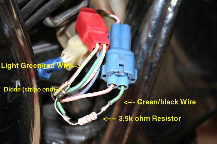
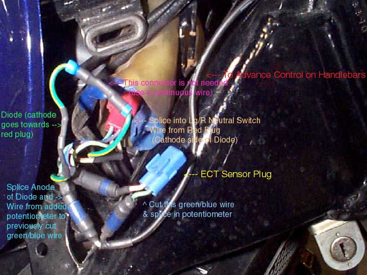
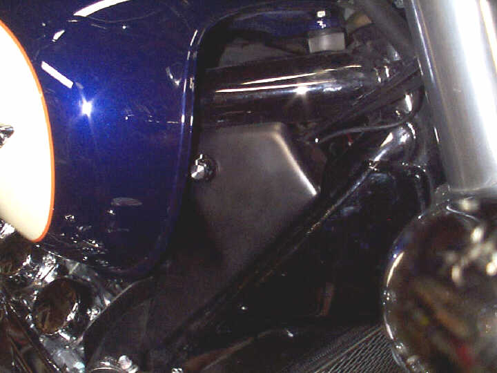
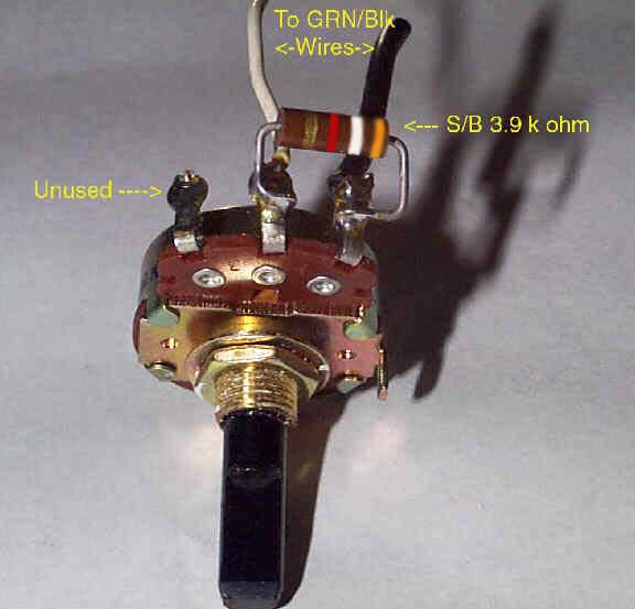
This modification is made to install under the right plastic neck cover, with the optional control Potentiometer installed in the neck cover. To start with, you'll need to remove that plastic neck cover. There is a plastic screw/plug to the left of the cover. The inner plastic screw needs to be removed from the plug that it sets in. (Unbolt the fuel tank and prop it up in the front for easy access). Use a small screwdriver to back out that screw and then pull out the plug. You can also gently pry out that screw by using a thin blade screwdriver (or an exact-o knife). Carefully stick the blade into the round crease between the plug and the screw and pry the screw up a bit and remove the plug. Now the cover is held on by a tab pushed into a grommet. Just gently pull the cover off. You should be able to see a bundle of connectors there under a semi-translucent protective covering. You are only interested in the red connector and the blue connector. They don't have to be disconnected, just accessed. Start with the blue connector that has two wires to it. Ignore the pink wire. You want the green wire with a thin BLACK stripe in it. You will want to cut that wire and solder the Resistor in between. Next, solder the Diode on after the Resistor (left side); MAKING SURE that the white stripe on the Diode is FACING AWAY from the Resistor. (See Picture 1) Next, find the red connector that has four wires coming from it. You want the LIGHT GREEN wire that has a thin red stripe in it. You don't need to cut this wire. Slide a Quick Splice Connector over the light green wire with the red stripe. Then place a 2 inch long wire all the way into the remaining hole of the Connector. Making sure that both wires are in the right place, squeeze down that metal tab and close the cover. Solder the end of the Diode to the 2 inch piece of wire you spliced onto the light green wire with the red stripe. Now, although Subman soldered directly to all the wires (without the use of a Quick Splice Connector) it should look like his picture (see Picture 1) If you do not want a Pot, you can stop here and tuck everything back up into the plastic sleeve and replace the cover. You are done. If you got everything right, the engine will idle as normal while in neutral but will pick up an additional 300 +- RPMs when in gear. Shift back into neutral and the RPMs will drop back to normal. Optional Potentiometer (Pot)If you want the pot, you should solder the 3.9kohm resistor to the center lead and one of the outside leads of the pot. (See Pic) This will give you better control over the timing. The pot needs to be spliced into the Green/black wire from the two wire blue connector. (See Picture 2) You can put the pot anywhere in the plastic cover that you want, but you need to make sure there is room for the pot when you put the cover back on the bike. There is an open area to the left where the tab goes into the grommet. If you drill a hole 3/4" behind the tab and even with the bottom of the tab, all should be fine (see the attached picture). In a perfect world, the hole would need to be 9/64". A 5/16" bit will work okay. Or you could use a 1/4" drill bit and just widen the hole some until the pot goes in. There is a little tab on the pot that is intended to keep it from spinning when installed. If you install the pot once and take it off again, it'll probably leave a mark where to make a little hole for that locking tab. Or you could just bend the tab down out of the way and put the pot on. There is very little force needed to turn the control, so it isn't really going to spin. Now, put the knob on using a very small screwdriver that I hope you all have. At least it wasn't an Allen wrench screw. Put the plastic cover back on carefully, because now you have a knob in the way of the tank and a pot in the way of the wiring bundle. I would put the plug half (without the screw, yet) into its spot first. It is handy to have some hemostats to squeeze that plug together to get it in that hole. (see Picture 3) How it works with the Pot.When you bike is cold, the control knob will have no effect at all. When the bike warms up, the optional knob will advance the timing from stock timing to 10 degrees advance. The pot was selected and customized (adding the 3.9kohm Resistor) to give you approximately half of that advance when the pot is turned half way up. The very beginning and the very end of the adjustment will not do anything. That was to insure you could turn the advance completely on and completely off.
*NOTE: If you have other electronic stores available, you can probably find a smaller pot. The on/off switch part of this pot is not needed (but could be utilized). Using the pot will require more wire, and especially if you want to mount it remotely) Credits: BlueValk for the initial write-up and Pic 2 & 3 Subman for Pic 1
|
||